NotaFanofWatkins
-
Posts
2 -
Joined
-
Last visited
1 Follower
NotaFanofWatkins's Achievements
Newbie (1/5)
1
Reputation
-
77119 Heater Relay Board Multiple Failures
NotaFanofWatkins replied to geo1111's topic in Portable Hot Tubs & Spas
You'd have to show us pictures of your whole setup. Technically the only difference between the 120 and 220 systems is one extra hot leg and the wires are moved around. I don't have a 220 setup, so I can't help you 100%. If you popped the GFCI, it's possible your GFCI is old/weak, but more likely that you have some current leakage to ground. AKA: Your heater probably has a short to ground and it's not safe. 100% do not mess around with GFCIs. If it tripped open on immediate powerup, you have a safety problem. It's possible your board was preventing heater power-up because it detected a short. I don't know for sure. -
NotaFanofWatkins joined the community
-
77119 Heater Relay Board Multiple Failures
NotaFanofWatkins replied to geo1111's topic in Portable Hot Tubs & Spas
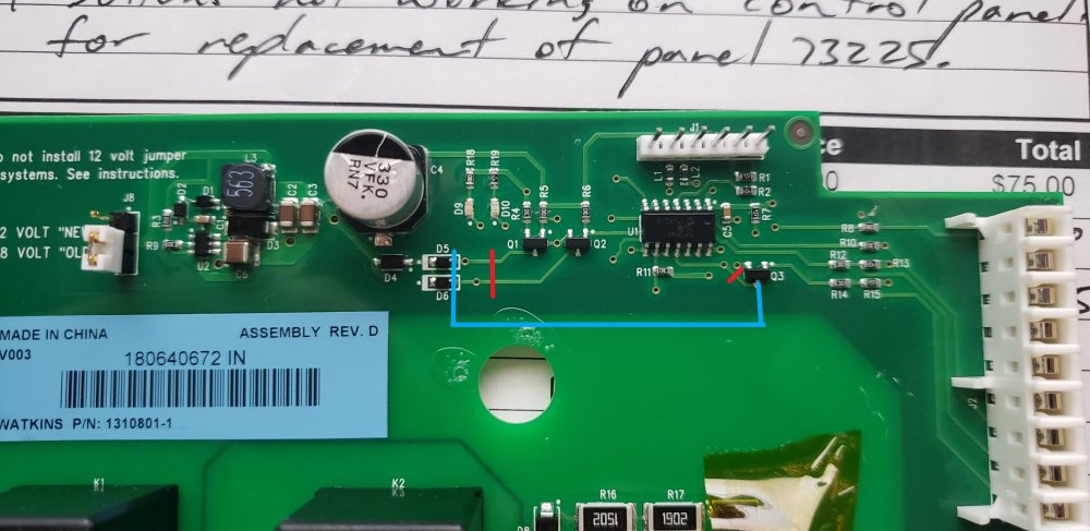
Hey friends. If you're like me, you've got one of these new IQ2020 77119 Relay boards with a flashing D9. Your heater works fine, your relays are good and they test out OK. D9 flashes on this guy for no reason and of course the manufacturer doesn't care about your plight. They want another $150 to $250 out of you, once again because of their crappy design. I can't help everyone with this board, due to the litany of configurations that it can be installed with. But if you're a 120V installation with no frills, no additional pump, no fancy motor hookups, etc. Then this may be for you. This procedure requires some comfort with electronics work and a small soldering iron for doing fine soldering work. See the picture at the bottom of the post for a diagram. Cut the traces on this board (marked in red) between D5 and Q1, D6 and Q2, and U1 Pin 11 and Q3. This last trace must be cut close to the Q3 transistor as there is a through-hole near Q3 that pulls Q3 to 5V and you don't want to backfeed the U1 IC with 12V unless you want it to pop open and spill it's guts. Pull a wire (in blue) on the right side of the D5 and D6 diodes to the middle pin on Q3. Now when a signal is sent to Pin 9 on the relay board, Q3 will turn on and latch the two relays to ground causing them to close. A technical explanation follows: In my installation, this board receives 5V on pins 5, 20V on pin 6 for relay/transformer power, and 20V on pin 9 for activating the heater relays. (Pins numbered from top to bottom) Pin 5 powers the IC circuit and small components on the board. Pin 6 powers the transformer on the left side of the board, converting the incoming Pin 6 power to 12V depending on the position of the 12/18V jumper. Pin 9 is dropped to ~ 1VDC through R15 and R14, and feeds Q3 which pulls the emitter of Q3 to ground when the call for heat is made from the main relay. The relays are always hot (12V) on their positive rails. When the relay board wants the relays off, they pull the negative rails HIGH (12V) to cause the relays to have no voltage drop across them. With no voltage drop, there is no "negative" rail and the relays remain open. The switching of the relays is done by Q1 and Q2 pulling these rails up to 12V by default. So any failure in the IC causes these rails to float up to 12V and the relays are permanently off. By chopping Q1 and Q2 out of the circuit, you can pull these rails LOW and cause a 12V voltage drop across the relays, thereby closing them. We need Q3 to do this work for us. Bridging the rails from D5 and D6 to Q3 does this job. D4, D5 and D6 must remain connected because they are flyback diodes that handle the voltage spike that happens when the relays open. If you have any other equipment run by this relay board, such as a blower motor or a secondary pump, this may not work for you at all as the relay board is getting several signals from the main control board. But if you're like me, and all you need is heat, this will work for you. What does doing this surgery mean otherwise? Well this board will no longer measure current and voltage from the mains supply, and it won't make any (maybe safety?) decisions about when/if to shutdown the relays. However, none of the prior versions of the board did that nonsense either, and Watkins was happy to ship boards that blew holes in the PCB for years, so take that for what you will. Personally, for me it was either work around this dumb problem or buy a new hot tub without this garbage inside it. There's no way I was about to spend good money on another board that chokes over a power outage/brownout/etc. I hope this helps you!