


seb101
-
Posts
8 -
Joined
-
Last visited
Everything posted by seb101
-
I think the total inaccuaracy of the test strips was causing me to massively over-dose the spa. For the last few days I've stoped the bromine dosing after use and just given it the oxy-shock, along with the bromine float dispenser. All seems fine now.
-
The spa is a 2012 J-465 model. The plumbing was purged and the filters changed a couple of weeks ago. The water is always perfectly clear, but just the bromine level never got above 1-2ppm. I’ve now tracked this down to faulty test strips, after giving the tub a dose of bromine that should have sent it through the roof the strips were still reading 1-2ppm. Seems these strips just don’t work properly with bromine (despite stating it on the packaging). I got some new strips and they are showing levels consistent with my dosing. The faulty strips were also putting my water hardness at over 1000ppm whereas on the new strips it measures 200-300ppm where I expect it to be based on our local water company levels. The strange thing is… the faulty strips were recently purchased from a large reputable UK supplier… I won’t name them, but I won’t be buying from them again. Out of interest, how do others test their test strips? Just keep a few from the last batch and make sure the new ones match?
-
Jacuzzi J-400 Pillow Light/Holder Replacement
seb101 replied to seb101's topic in Portable Hot Tubs & Spas
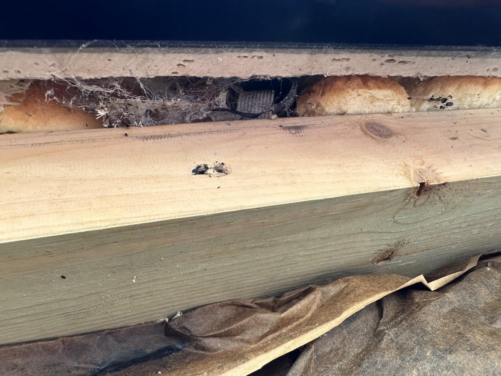
So the answer to this one turned out to be... yes, just get a saw and and get on with it I used an oscillating saw tool to cut a section out of the wooden support and that created enough room to dig out the insultation and with some swearing and finger strain, get the old light out and put the new light in (it goes through the hole where you can just see the daylight at the top of the image). I then wedged the wooden section back in and secured it with some metal jointing plates.
-
OK, so I'll share my learnings here for future tubbers to use if they need! As expected the control system is a simple 5-wire RGBWV+ and operates at 15V. There are two 5-wire connectors that originally plug into the Jacuzzi controller to the DCUs (one each side of the tub), the wiring is as follows: Wire LED Green RED Red 15VDC + Yellow BLUE Black GREEN White WHITE From the DCU to the lights Jacuzzi use a 10-wire ribbon cable, in which the wires are paired cleverly to mean the connector can be inserted either way up and still work. PIN LED 1 & 10 15VDC + 2 & 9 WHITE 3 & 8 RED 4 & 7 GREEN 5 & 6 BLUE So it was ultimately very trivial to fix. I bought a cheap wide-voltage-range RGBW LED controller from AliExpress and cut into the lighting wires at the old control box end. Wired the appropriate wires into the controller and switched it on. Worked first time. Also worth noting that while the original Jacuzzi system ran 15VDC the LEDs work just fine on 12VDC with acceptable light output. There are no white LEDs in the original Jacuzzi in-tub lighting so this ends up unused - except for the Bonus item below. Bonus: This tub has a light-up logo on the front which originally was used to identify fault conditions, it can glow White or Red depending on Normal/Fault. I've yet to work out if I can get this fault logic to work with the Balboa system, but for now I just hard-wired it to glow white when the rest of the LEDs are on. The logo cable is different and is wired as follows: Wire LED Red RED Black 15 VDC+ Brown N/C Green N/C White WHITE
-
I have a 1500L Jacuzzi 465 with a Clearray UV system, but no ozone generator. While I am able to maintain good non-use bromine levels using my float dispenser, but post usage the spa is always dropping to 0 free bromine levels by the next morning. Routinely there are only two of us using the spa, for an average of an hour. I've been steadily increasing my post-usage dosing over time but it seems to never be enough. Currently I'm dosing with 30g of non-chlorine oxy-shock and 30g of bromine after each use, which the manufacturer says should increase the levels by 3ppm - I would have thought this combined with the slow-release of the float dispenser would be enough to get back to normal level by the next morning, however this is not the case. Do I need to just keep increasing the post-use bromine dose until it works (seems expensive!)? Or is there something else I am doing wrong. PH and TA tend to deviate low, but I routinely correct this, however our water is on the hard side (measures 1000 ppm) and I don't know if this needs to be fixed or is contributing to problems. Any advice appreciated!
-
I need to replace the pillow holder/light on a J-400 due to the original having snapped and creating a leak point when the water level is high. I have the spare part but having removed the side from the tub I'm frustrated to find this part is almost completely inaccessible. Aside from an inpenetrable layer of thick foam insulation the part is also directly above the main support structure of the tub shell. As the pillow holder sits inside the tub 'edge' its also impossible to access from the reverse angle. What would you do in this situation? The only thing I can think is to cut a section out of the wooden tub structure out and then replace afterward with some splicing plates. This seems extreme, or is it par-for-the-course for tub repairs? Thanks. The part is at the upper end of the grey ribbon cable you can just see at the top of the photo.
-
In the absense of any information that I can find online, I'm going to attempt this myself! I have seen reference to enough mentions of '15V' for the LED system in Jacuzzi that I'm going to start with 15VDC as an assumption, if I blow anything up, I'm in no worse position as nothing works currently! Worse case, it might be 15VAC which will be a nightmare anyway as there are no generic VAC LED controllers on the market. The plan is: 1. The BP2100 outputs 10VDC 5A max on a 'lights' circuit, I'll pass this through a DC/DC buck converter to get 15VDC and apply this to the DCUs and see if I get any light output at all. I'm hoping this will light them up in a deafult state but also may do nothing if there is no control signal. 2. I have to assume the 5-wire control system is RGBWV+ it's unclear if this runs on the same 15V as the DCUs but in the absense of any other information I'll assume it does. The trickiest part is going to be working out the assignment of the wiring pins, reversing the polarity on an LED can zap it instantly so I'm going to experiment on a broken pillow light fixture that needs to be removed in any case. 3. If the bench tests prove positive I'll wire in a Zigbee enabled 12-24VDC RGBW lighting controller and go for it! Watch this space...
-
Hi all, Does anyone know the details of how the LED lighting controllers (DCUs) on Jacuzzi tubs are wired/controlled? I have inherited a J465 tub that was 'upgraded' at some point with a Balboa BP2100/TP800 control system. Whoever did the conversion managed to keep the Audio system working but evidently gave up on the lighting. All the LED wiring is intact but left disconnected inside the housing. What I appear to have is 2 blue 'DCU' distribution boxes, one on the right and one on the left of the tub, these are still wired up to the individual LED lights in the footwell, headrests, cup-holders and waterfall. Presumably, the DCUs needed a power connection and a control signal to command them to specific colours. There appears to be 3 cables from each DCU, which I believe are: 1. Power (2-wire) 2. Power Switch (2-wire) 3. Control (6 wire) Does anyone have any insight into how these DCUs are controlled? Is it a proprietary control signal? Or is it a simple RGBV- or RGBWV- type LED control found in typical LED strips? Also, does anyone know what voltage the DCUs and LEDs are supposed to run on? Thanks!

