jsharpe
-
Posts
6 -
Joined
-
Last visited
-
Days Won
1
jsharpe's Achievements
Newbie (1/5)
1
Reputation
-
77119 Heater Relay Board Multiple Failures
jsharpe replied to geo1111's topic in Portable Hot Tubs & Spas
Update - 2 I removed the suspect chip and installed a socket and a brand new device. I also cut back the metal bracket to give plenty of clearance (not sure why I can't include another picture, but it won't let me saying the size it too large even though it is way smaller that the stated limit). Anyway skipping to the end game it didn't change the behavior. So the issue must be something else on the board. Time to order a whole new one now... -
77119 Heater Relay Board Multiple Failures
jsharpe replied to geo1111's topic in Portable Hot Tubs & Spas
Update 1 - Further inspection showed that one pin in the optocoupler had indeed made contact with the metal bracket through the protective sheet(see attached). So replacing it seemed like a reasonable thing to try.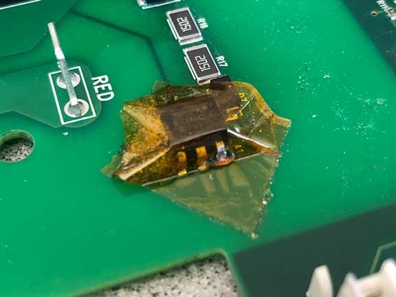
-
77119 Heater Relay Board Multiple Failures
jsharpe replied to geo1111's topic in Portable Hot Tubs & Spas
Hi George, Extremely helpful!!! I was kind of hoping there would be someone with your knowledge lurking out there and willing to share, but wasn't holding out much hope. I had similar thoughts about the tape covering that one chip. Why the extra precaution? Especially since I could have sworn that earlier instances of the board didn't have the tape. It does sit very near the metal brackets but didn't seem that it was likely to short against them. Made me wonder what they were worried about. I'm guessing that my new replacement board will eventually fail like all the others, so I'm motivated to get to the bottom of the issue. Since the rest of this failed board looks to be in great shape and I know the relays are fine, it makes sense to try replacing the optocoupler rather than just tossing it. Just in case it does turn out to be that component and swapping it out solves the problem, I think I'll order a few of the sockatable versions so the next time it fails I can just pop a new one in. I might end up having to rig up a ribbon cable to get it clear of the brackets, but that shouldn't be too tough with only 6 pins and it's not exactly a high frequency circuit that I have to worry about introducing noise. In fact it might even be easier to do it that way instead of dusting off my surface mount soldering skills. Of course the "right" answer would be to figure out what was causing it to fail and address that issue, but I figure that's a much tougher problem and probably one for the manufacturer. Thanks much for your help. I'll let you know how it turns out, although it might take few weeks as I'm a bit slammed right now. -
77119 Heater Relay Board Multiple Failures
jsharpe replied to geo1111's topic in Portable Hot Tubs & Spas
Understood. I've done the cycle things many times and when this failure mode occurs it doesn't help. After the power on sequence completes the red led on the relay board flashes and the heater doesn't energize even when the main board is telling it to. I suppose that there might be some condition that is somehow fooling the control circuit to incorrectly think there is a fault in the relays and so it de-energizes them and blinks the led. Although the root cause of the failure might indeed be somewhere else in the system besides the relay board. In my case, every time this has happened replacing the relay board with a new one has resolved the issue. That tells me the failed component resides on the relay board. What it doesn't say is whether the cause of the failure originated on that board or not. For example, it's possible that something on the main board is somehow frying a control chip on the relay board. So replacing the relay board is only a temporary fix until the external cause breaks it again. So I go back to my earlier comment that it would be very useful to know exactly what component(s) have actually failed. Everything I found always says "its the relays". But, at least in my case, it most definitely is not the relays. They're just fine. But that doesn't change the fact that the spa doesn't heat and instead just blinks irritatingly at me. -
77119 Heater Relay Board Multiple Failures
jsharpe replied to geo1111's topic in Portable Hot Tubs & Spas
In my case neither relay is bad. It is something in the circuitry that activates the relays located on the relay board that "died". If I had to guess it's one of the small IC's since they would seem to be the most fragile. Unfortunately, testing those is a bit more involved than the relays and would really be better done with the aid of a schematic. Which I don't currently have but I suppose might be floating around somewhere. If I could identify which component actually failed then your question becomes the most important. "Why did that component fail?" And the obvious follow-on, "what can we do about it?" Given how cheap those chips probably are, it might make more sense to socket them and just pop a new one in when needed rather than reengineering the circuit to better protect them from surges or whatever is the root cause. -
77119 Heater Relay Board Multiple Failures
jsharpe replied to geo1111's topic in Portable Hot Tubs & Spas
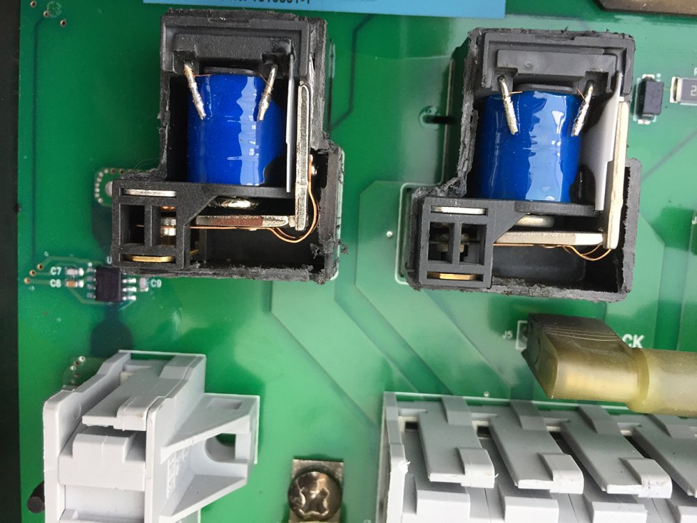
I've had an almost identical experience with a 2002 Grandee. The only difference is that the time period between relay board failures is a bit longer. I'll get closer to a year between failures, but I've had 4 now. Three of those have been with the newer board design. The symptoms are always the same as those described above. This time however I decided to do a bit more investigation rather than just blindly replacing the board again (which I'm sure will fix it, at least for a while). I removed the board and inspected it for any visible signs of damage, both front and rear and found none. Everything looked like new. Since I had found out that I can purchase replacement relays from the CIT for about $10 each I figured it would be worth verifying if one or both were bad since that would be a much cheaper fix than an entire new board (that will probably fail at some point in the future anyway. So I carefully cut the top of the plastic housing off the two relays to inspect the armatures and contacts. CIT actually makes a different version of this relay that doesn't have any cover so I didn't figure it would alter their operation, for example if the internal components were mounted to the inside of the cover. Although the contacts on one were slightly corroded, they still made a reliable electrical connection. I then tried energizing them and they both operated normally. There was nothing wrong with the relays! I then reinstalled the board and observed that the flashing red light returned and although the main board was calling for heat, neither relay energized. This says to me that the flashing red light might indeed actually mean that the relays were failing to operate, but at least in my case, it's not a problem with the relays, but rather something with the control circuitry. Because replacing the relay board has always resolved the problem in the past, I'm thinking that the issue must be one of the chips mounted on that board (as opposed to something wrong on the main control board). In case anyone's interested, here's what the inside of the relays look like. It's really easy to see that the armatures don't move when the spa is powered on and calling for heat.