jkillion
-
Posts
8 -
Joined
-
Last visited
jkillion's Achievements
Newbie (1/5)
0
Reputation
-
Balboa vs504sz - pump 1 runs only on low speed
jkillion replied to jkillion's topic in Portable Hot Tubs & Spas
Swapping black and red has no effect. Just one speed, slow, regardless of which wire is sending the power. The power cable is brand new as well, I replaced it when I replaced it after the pump thinking that might have been the issue. No change. -Jud -
Balboa vs504sz - pump 1 runs only on low speed
jkillion replied to jkillion's topic in Portable Hot Tubs & Spas
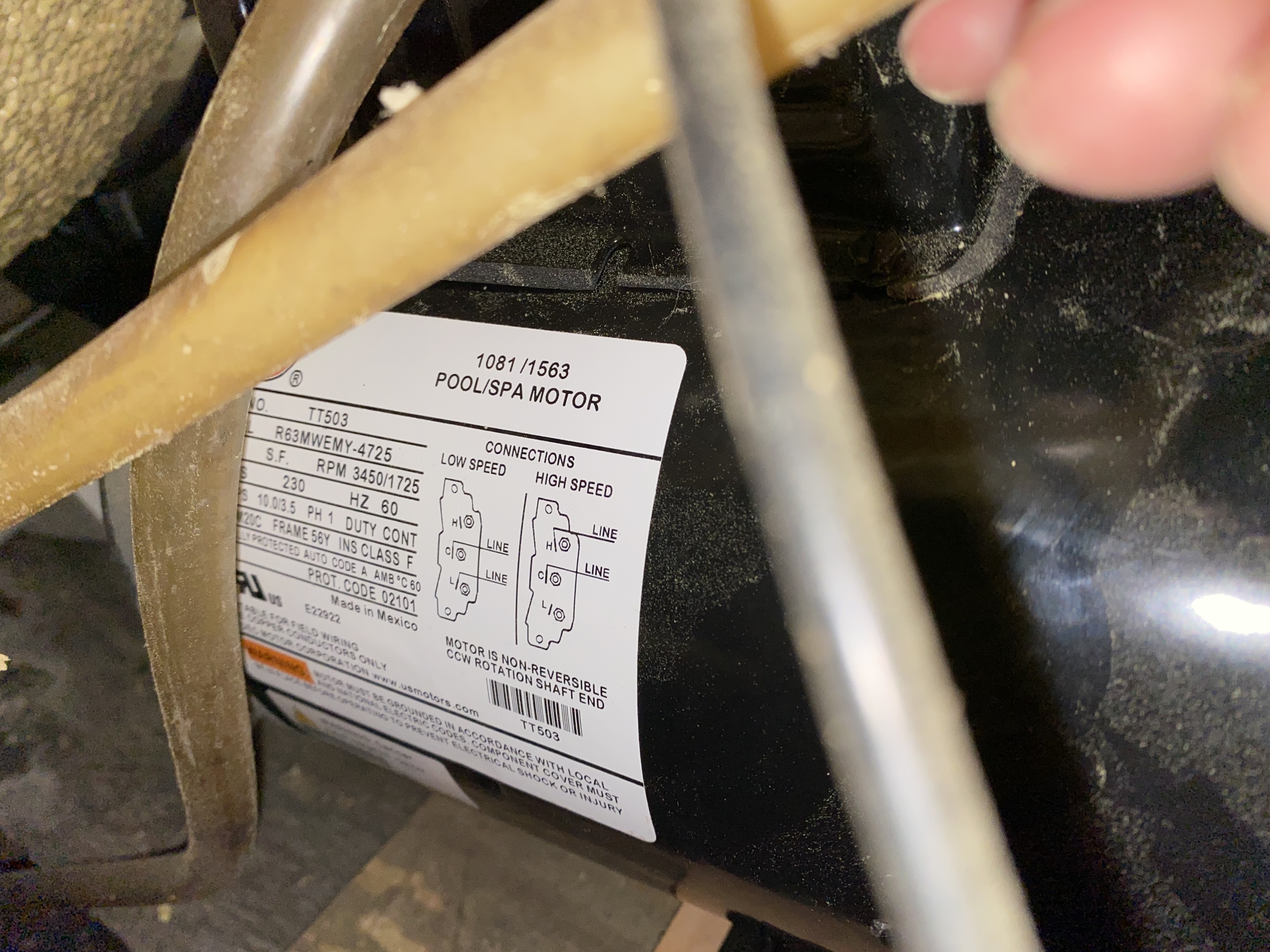
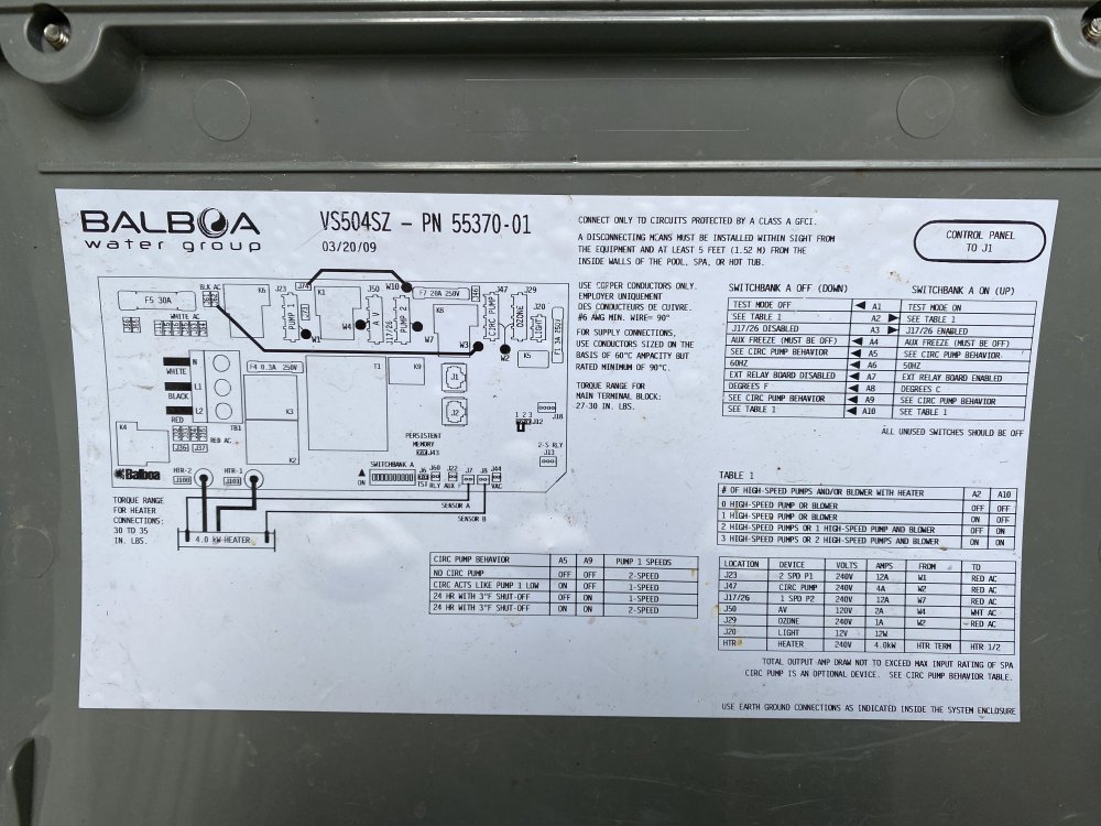
Attached are pictures of the pump plate and the wiring. thanks!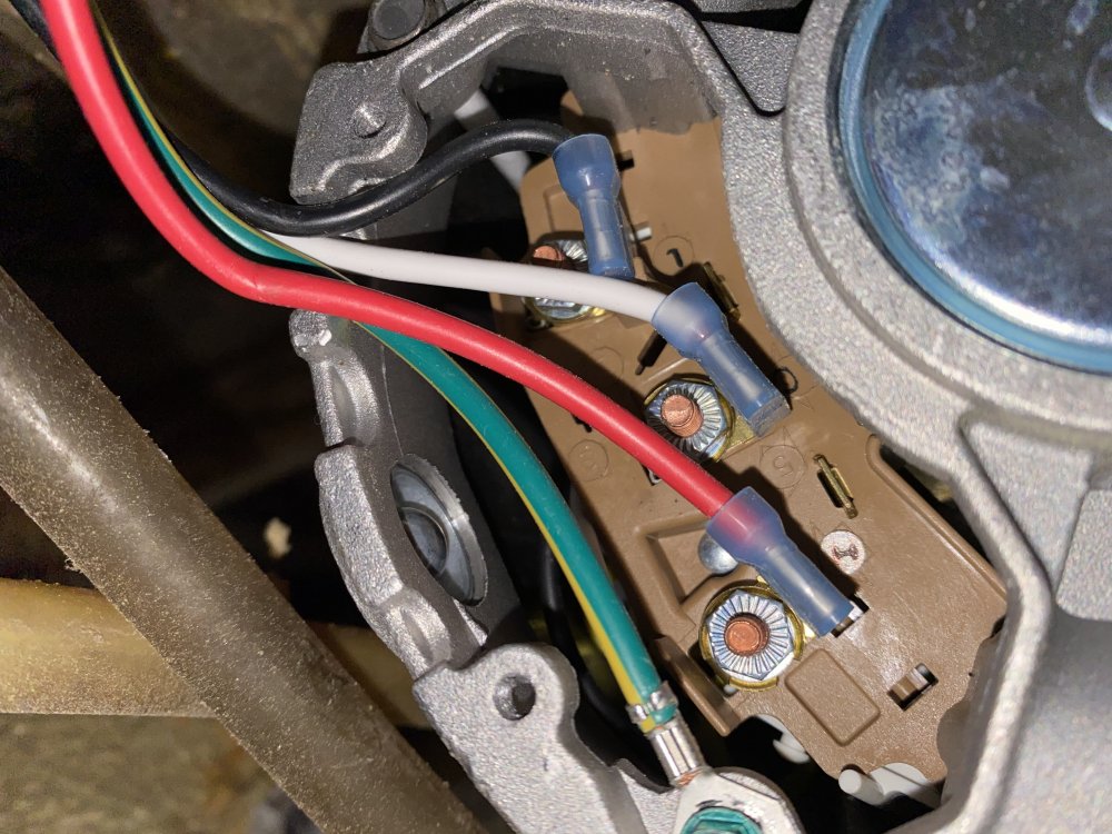

-
Balboa vs504sz - pump 1 runs only on low speed
jkillion replied to jkillion's topic in Portable Hot Tubs & Spas
Ok, I’ll try and see if I can get some pictures to that effect. If I just swap the AMP plugs for Pump 1 and Pump 2 (currently a single speed pump that does work), can I do a quick test to see if the pump works well when plugged into Pump 2? Or will that screw something up? My thinking is that Pump 2 is currently only sending high speed to a single speed pump, maybe it’ll make my dual speed pump actually go into high gear? Obviously not a fix or something I’d run more than a couple of seconds, just trying to think about how to eliminate things. Ill get those pics as soon as I get the kiddo to the grandparents. thanks! -
Balboa vs504sz - pump 1 runs only on low speed
jkillion replied to jkillion's topic in Portable Hot Tubs & Spas
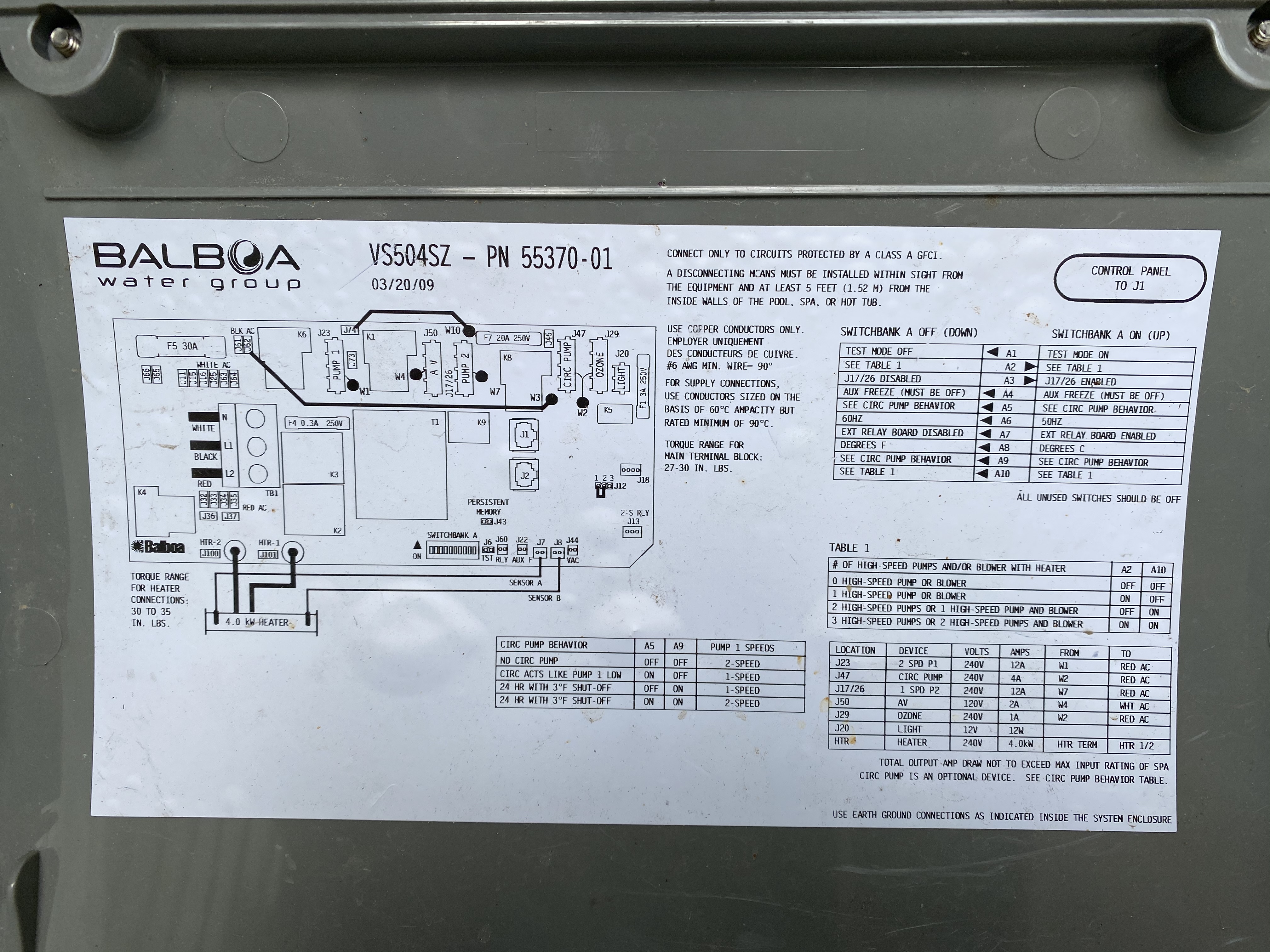
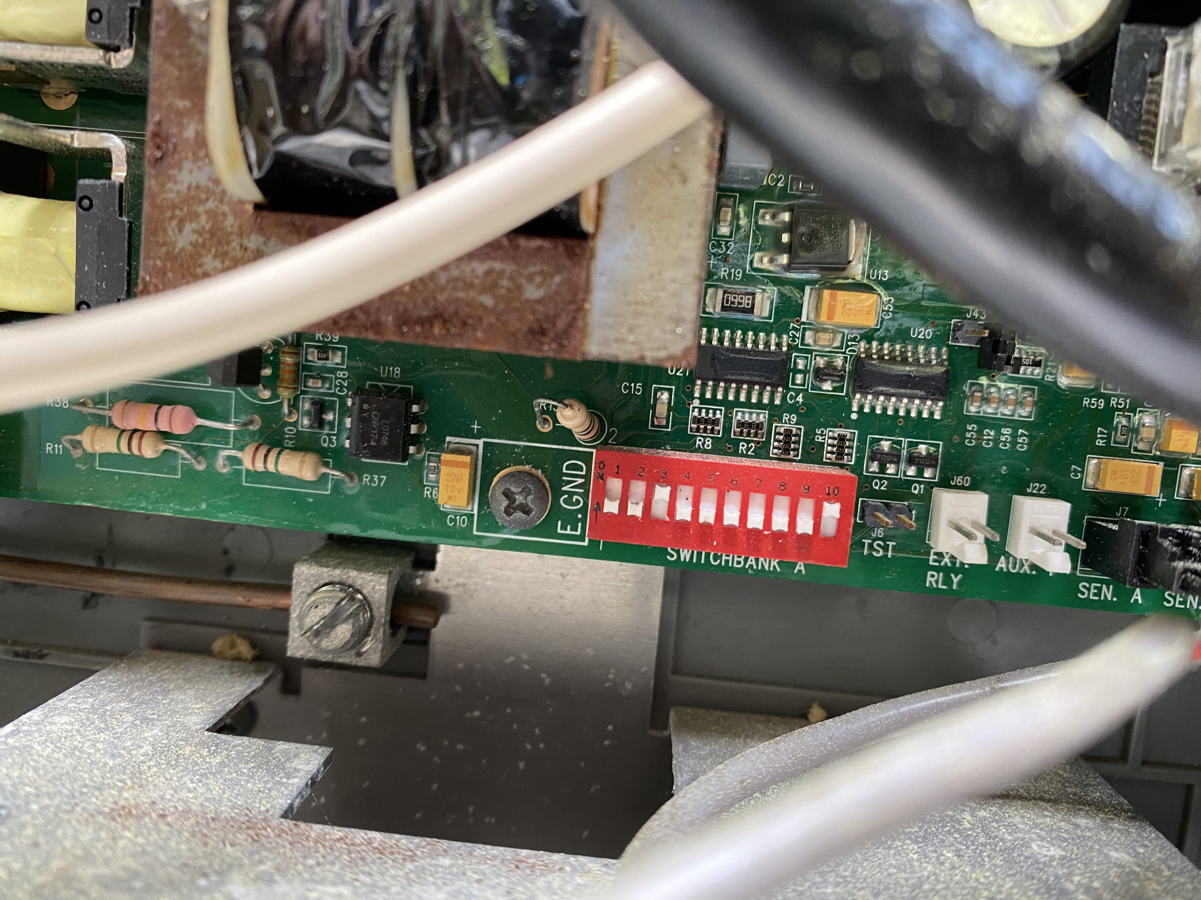
Since I’m sure you guys will be asking for them, here are some control pack pics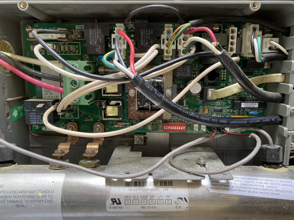
-
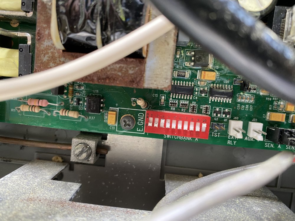
Hi folks, I recently got a free hot tub. Hawkeye, from around late 2000s. When I got it the pump was completely frozen (220V 56 Frame 3HP AO Smith 2 speed), so I bought a new pump (Waterway executive 56, 3hp 2 speed 220v). The issue is that it only seems to run on the low speed. Here is a layout of the system I have. Service: 220V, verified 220 going into the spa pack. Control Pack - Balboa VS504SZ Pump - Waterway 3721221. 10.0/3.5A I believe. Wired with the black wire (Balboa low speed) going to the low on the pump, the red wire going to the high, the white going to the common. The pump circulates the water and heats it up, when I press Pump 1 on the control panel to engage the high speed, I hear a click, it *sounds* like the motor is trying to go to a higher speed, but there is no difference in the output on the jets. When I press pump 1 again the pump cuts off (as expected, unless the heater is going then it just stays on). So, here is what I have done to diagnose it. Pump 1 Low speed: 220volts between black and white. Used a clamp on amp meter. Amp draw on black wire is 3.5ish (it is a 10/3.5 pump, so that is what I was expecting). Amp draw on red wire is nothing substantail (< .2A, but it could be residual stuff or my amp meter) Pump 1 High speed selected: 220volts between red and white wire. 5.9A draw on the red wire, low (again < .2A) on the black wire. This was not what I expected. Since it is a 10A pump, I assumed that it would draw closer to 10A. Any ideas of stuff to try? All the dips look like they are in the right place for my setup, and the jumper wires all look like they are going to the right place according to the sticker on the spa pack cover. Does it seem like a problem with the VS504SZ board, or did I just get a crappy pump? Any way to isolate whether its a pump problem or a board problem? Any help would be appreciated! Thanks!
-
Hotsprings Highlift Model K Hot Tub Not Heating
jkillion replied to jkillion's topic in Portable Hot Tubs & Spas
Yep, its a 1995. To check the voltage, which terminals do I need to test across when it is trying to heat. Lets assume it has a layout as follows for the relay looking down at it: A B space space C D E F The spaces are just dead space (tough to do this in text Here is the voltages: C-D 240V E-F 50 or 60 volts C - ground 120v D - ground 120v E - ground 130v F - ground 60v I haven't done anything testing from A-B or either of those to any other terminal. I will go ahead and grab 34321, but in the mean time if you let me know which terminals to test the 12 volt part that would help! Thanks, Jud -
Hotsprings Highlift Model K Hot Tub Not Heating
jkillion replied to jkillion's topic in Portable Hot Tubs & Spas
Thanks! Some additional info. I checked the power from the breaker box to the control unit. 240v. I checked the power going to the heater relay, 240v. (120 on each side of the relay, combined 240) The power coming out of the heater relay is messed up as above. I thought relays for the most part were open or closed. Would a heater PCB make it just open on one side and half open on the other? Is this the part you are talking about for the heater PCB? http://www.backyardplus.com/proddetail.php?prod=71341&cat=258 Thanks, Jud -
Hi, My hottub is not heating. Here is what I have done so far. 1) Verified that control and high limit thermistors are working correctly and reading correctly. Ohm reading across the thermistors compared to chart and current water temperature 2) Verified that the flow switch is working (near 0 ohms when circulating pump is running) 3) Verified that heater is not broken working by checking resistance across two load wires (~9.8 ohms) Here is the rub. When I check the wires running to the heater I am getting the following readings via multimeter set to 600volts AC (lets assume A and B are the voltage wires and G is the neutral wire) A-G - 140volts or so B-G - 57 volts or so A-B - 59 volts or so I think it should read more like A-G, B-G being 120 and A-B being 220 or 240. What causes this type of symptom? I know its not heating because the heater isn't getting the correct amount of juice to do its job. Is it a bad heater relay or something? Thanks for your help. Jud